Boldport Cordwood Puzzle Too
This post is about building the Boldport Cordwood Puzzle Too which is described as:
The puzzle is to correctly assemble the circuit with the components at hand. Once completed, all LEDs light up when power is applied. When connected to a controller board each LED can be individually controlled.
It is a sequel to the Cordwood Puzzle 2nd Edition which I’d built previously by following the online assembly guide. This time I wanted to figure out some of the details for myself.
The build
I normally use masking tape to hold the components on the board so that I can clip the leads short before I solder them, and use a third-hand for holding the board while I solder. But this time I experimented with using Blu-Tack for both purposes.
Contents
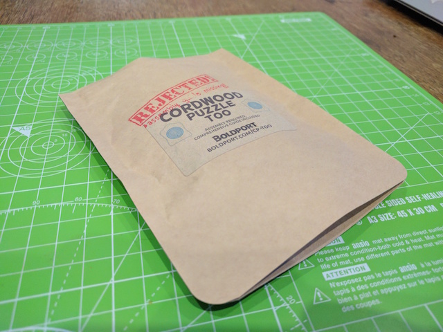
The project comes in this lovely packet which seems a shame to tear open:
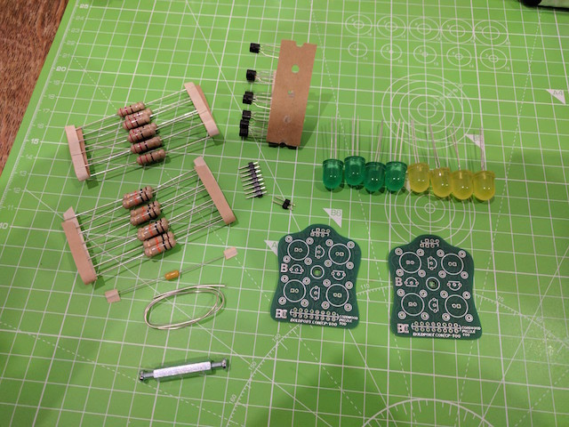
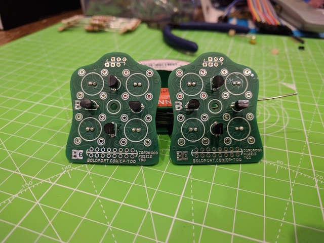
Inside are the components and two identical boards:
MOSETs
I started with the eight MOSFETs because it wouldn’t be possible to access them once the LEDs were in place. Their position and orientation are helpfully marked on the silkscreen. I much prefer these kind with the bent legs that you don’t need to splay.
I first secured them to the board and clipped the leads short:
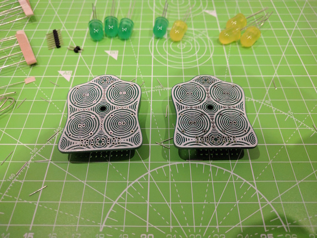
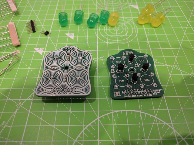
Then soldered them in place:
LEDs
There are four each of the plump green and yellow LEDs. I tested them using my Boldport LIGEMDIO:
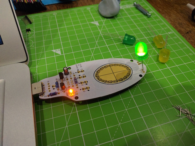
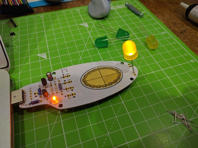
The pads indicate the orientation of the LEDs. The anode (longer leg, smaller plate) goes to the square pad (+ve) and the cathode (shorter leg, larger plate) goes to the round pad (-ve). I almost put them on the wrong side of the board and then realised my mistake at the last minute.
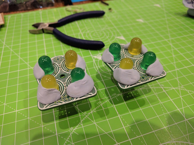
I secured them flush to the board so that I could clip the leads:
I soldered them and cleaned off some of the flux:
I considered attaching the headers next but decided to leave them because I thought they’d get in the way of the wires that connect between the two boards.
Understanding the circuit
There are two types of resistors in the packet; 220Ω and 10KΩ. The fact that they’re so large makes it easy to read the colour bands and tell which is which. I’d learnt from building the Cuttle that 220Ω (or thereabouts) is a common current limiting resistor for driving an LED and that 10KΩ can be used between +ve power and a gate to “pull it high”. So I knew how they were used, but not where on the board.
To understand the circuit a bit better I drew it out on paper while looking at the pads and traces. The traces are pretty squiggly and hard to follow in places, so I double checked them with a multimeter in continuity mode. The datasheet for the MOSFET shows what the three legs do.
Here’s the diagram of the back of the board:
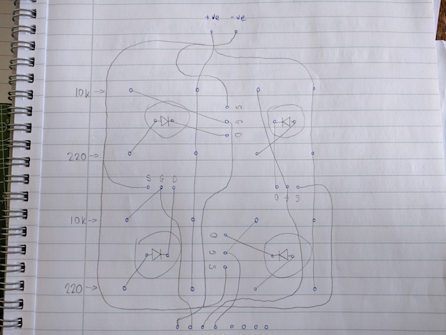
When the opposing board is joined with resistors then the vertical +ve rails get connected to the LED anodes and MOSFET gates. This turns all of the LEDs on by default. The gates are also connected to the headers at the bottom of the board. When one of those headers is connected to -ve, such as by a microcontroller setting the output to “low”, this causes an individual LED to turn off. This can be used to turn them on or off in an pattern.
Resistors
Based on this, I could tell where the different resistors went, which are grouped horizontally. I later found out that the placements for the 10KΩ resistors are marked with an asterisk on the silkscreen but I didn’t notice it at the time.
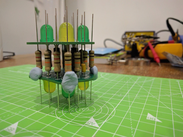
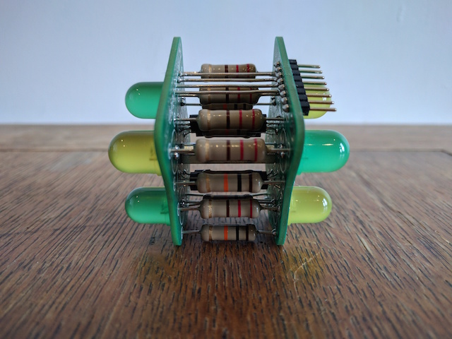
I dropped the resistors into place on one board:
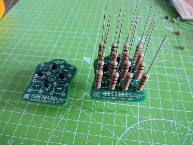
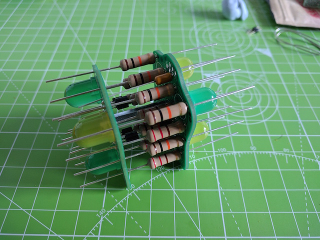
I attached the standoff to the other board because I wouldn’t be able to get it in position after the resistors were in. To get the resistors into the other board I stood both boards up facing each other in blobs of Blu-Tack. Then I guided the leg of each resistor from behind over to the other board, letting them rest in the middle:
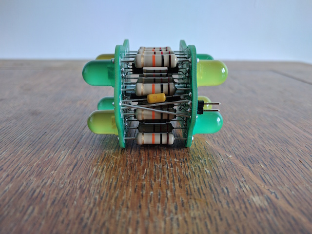
Capacitor
The 1uF capacitor has shorter leads so it can go in after the resistors. It’s acting as a decoupling capacitor so it needs to connect to +ve power on one board and -ve power on the other:
Joining the boards
I screwed the standoff into the other board so that the components couldn’t escape anymore.
The resistors needed to be lined up before soldering them in place. I was quite particular about making this look aesthetically right. So I tried a few solutions, which all failed.
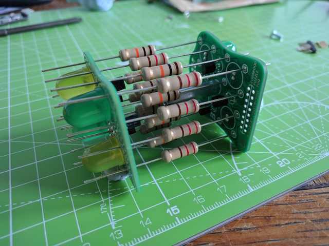
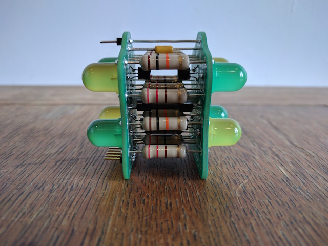
I eventually settled on standing the boards on their side and using a piece of card to evenly push the resistors into the centre. Luckily I had pulled them off the packaging tape instead of cutting them so they were all the same length. Then I secured the four resistors at the corners using Blu-Tack.
The four corners held all of the other leads at the correct height when stood up:
I soldered all of the resistor leads on one side. Normally I clip them short first, but I was worried about them moving position, so I had to clip them afterwards and touch up the joints.
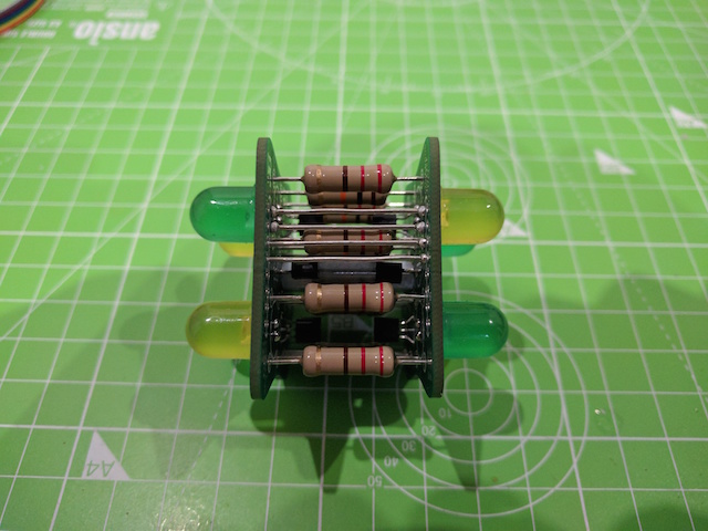
Then I clipped and soldered the leads on the other side. Except for the middle four, which I didn’t clip because I thought I might need to buy some new cutters to reach them between the LEDs:
I later managed to clip the middle four leads by cutting each of them down to about 5mm so that I had enough clearance and then angling the cutters down so that the nose was as close to the board as possible.
Headers and wires
Based on the diagram earlier, the eight pin header connects to four of the gates on the board. In order to connect the other four gates on the other board you need to attach wires that go straight between both.
The two rows of holes are connected vertically and I choose the top one so that the header could sit neatly at the bottom. It took a while to straighten out the wire and cut it to length. A little too much solder wicked through to the other side but I managed to tidy it up a bit later:
I added the eight pin header for the gates. I toyed with the idea of having it facing inside the boards so that it was tucked away, but it wouldn’t stand up straight when the wires were attached, so I put it on the outside:
I soldered the capacitor in place. Wires need to be added to carry the power from one board to the other, +ve to +ve (square pads) and -ve to -ve (round pads). Lastly the power header goes on +ve and -ve of the same board that has the eight pin header:
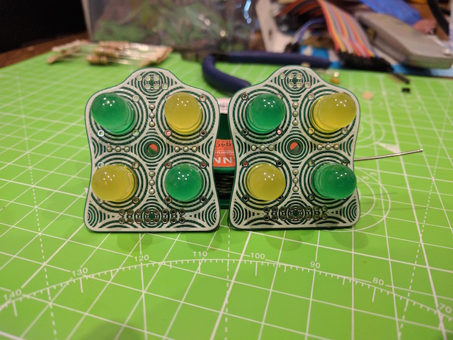
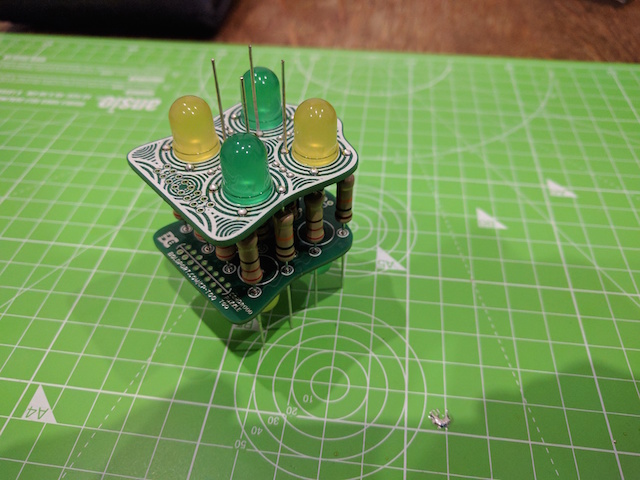
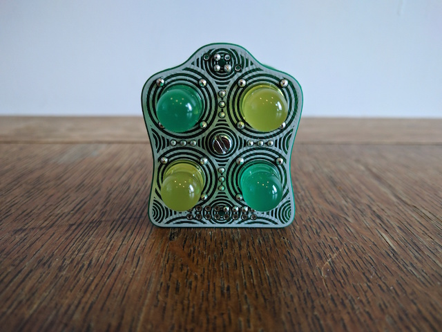
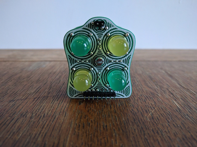
Completed
Here’s the end result after cleaning off the flux:
Here’s a video of it in action, being controlled by my TiLDA Mk3: