Boldport Cuttle (just less than perfect)
This post is about building the Boldport Cuttle which is described as:
The Cuttle is a bare-bones Arduino-compatible soldering kit. It’s based on the concept of shrimping.it, and was first designed as commissioned work for Embecosm, who made it open source hardware. This design, as always, is also open source hardware; it’s available on our GitHub repository.
More specifically, it’s about getting the Cuttle working from the “just less than perfect bundle”, as someone that’s pretty new to electronics and knew nothing about Arduino.
Sourcing components
I bought the bundle because it was cheap and gave me the opportunity to practice soldering on a variety of projects. The bundle only contained the PCBs so I had to source all of the components myself. I’d never done this before, but it was quite straightforward, because the page for each project lists all of the components you need and in most cases even links to the specific Farnell or Rapid product pages.
Some of the original components were out of stock, no longer available, or only available from overseas at a much higher price. I managed to find suitable alternatives for everything. In most cases I could get the same specification from a different manufacturer, or at a different error tolerance for not much more cost.
Some of the components were only available in multiples of 5 or 10. This was OK though, because it gave me room mistakes and they turned out to come in useful later.
Assembling the board
The Cuttle in the bundle is described as:
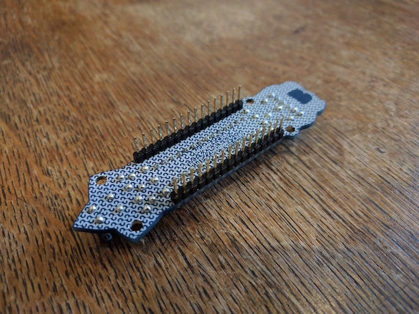
The manufacturer decided not to remove silkscreen from pads, and add their logo on the board. This didn’t fly. Soldering the board on the bottom side will be somewhat more challenging than normal, but otherwise the functionality is exactly the same as what members got.
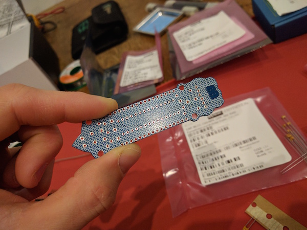
I wanted to improve my chances of the solder making strong and conductive joints. So I used a sharp knife to carefully scrape the excess silkscreen off of the surface of the pads. It took a while, but it was quite therapeutic. Testing with a multimeter in continuity mode on the surface of the board confirmed that it had worked.
Here’s a picture of the board afterwards with shiny exposed pads:
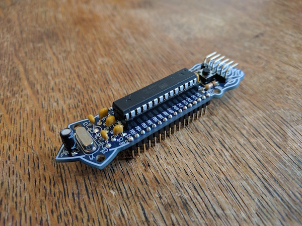
Adding the components was straightforward. The silkscreen tells you everything that you need to know. The end result looked like this:
Initial attempt at connecting
Before starting the project I knew that I’d need something to connect to it with. In preparation, I bought a cheap CH340G based USB to serial adapter that I’d seen @tardate refer to.
I downloaded the Arduino IDE, connected all of the wires on the serial header (except CTS which apparently isn’t needed), and tried uploading the basic “blink” sketch which makes an LED connected to one of the headers flash. I got this error:
avrdude: stk500_recv(): programmer is not responding
avrdude: stk500_getsync() attempt 1 of 10: not in sync: resp=0x00
Then I remembered something that I’d read on the original Cuttle project page:
The microcontroller comes with an Arduino bootloader on it, but you’ll need a serial programmer to load Arduino sketches to it.
The stock ATmega328 chip that I’d bought didn’t have a bootloader so the Arduino IDE couldn’t talk to it. There are few common ways to flash a bootloader onto a chip but they all require hardware that I didn’t have, such as a dedicated AVR programmer, another Arduino, a parallel port, etc.
But I did have a Raspberry Pi that has a bunch of GPIO pins. I started researching and found a few guides that helped:
- https://learn.adafruit.com/program-an-avr-or-arduino-using-raspberry-pi-gpio-pins?view=all
- http://kevincuzner.com/2013/05/27/raspberry-pi-as-an-avr-programmer/
- http://blog.stevemarple.co.uk/2013/03/how-to-use-gpio-version-of-avrdude-on.html
None of them covered exactly what I needed. So if you find yourself in the same position..
Connecting at 3v3
Two of the guides that I’d read say to connect the Arduino to the RPi’s 5v output. Whereas another guide says that you must absolutely not do this unless you’re using a voltage divider or level converter on any pins that input into the RPi, because the RPi isn’t 5v tolerant and can be bricked. I chose to believe the latter.
I had some spare resistors that could be used make 5v to 3v3 voltage dividers. However I wasn’t confident which of the pins needed them; definitely MISO (Master In Slave Out), maybe RESET (because it’s pulled high by a 10k resistor connected to VCC), maybe others when the Arduino restarts?
So I decided that connecting at 3v3 was easier and safer. When using the 16Mhz clock on the Cuttle it would mean that I’d be essentially overclocking it, but only for a short period of time and it was probably going to be OK. Besides a new ATMega328 was cheaper than a new RPi.
These two diagrams were really useful for finding the relevant pins:
There are two groups of SPI pins on the RPi. I used SPI0 because they’re neatly clustered together with the 3v3 and GND pins. Here are the exact connections that I used:
- ATmega328 VCC (physical 7) <-> RPi 3v3 power (physical 17)
- ATmega328 GND (physical 8) <-> RPi GND (physical 20)
- ATmega328 RESET (PC6, physical 1) <-> RPi CE0 (BCM8, physical 24)
- ATmega328 MOSI (PB3, physical 17) <-> RPi MOSI (BCM10, physical 19)
- ATmega328 MISO (PB4, physical 18) <-> RPi MISO (BCM9, physical 21)
- ATmega328 SCK (PB5, physical 19) <-> RPi SCLK (BCM11, physical 23)
Configuring avrdude
avrdude is used to flash the bootloader. Unlike older guides, you
probably shouldn’t need to compile it yourself to get linuxgpio support.
If you’re using a variant of Raspbian OS then you can use:
apt-get update
apt-get install -y avrdude
You’ll need to configure ~/.avrduderc so that it knows which pins the
Arduino is connected to. The numbering is “BCM”, not physical:
programmer
  id    = "linuxgpio";
  desc  = "Use the Linux sysfs interface to bitbang GPIO lines";
  type  = "linuxgpio";
  reset = 8;
  sck   = 11;
  mosi  = 10;
  miso  = 9;
;
You can run the following command to confirm that it works:
# avrdude -p m328 -c linuxgpio

avrdude: AVR device initialized and ready to accept instructions

Reading | ################################################## | 100% 0.00s

avrdude: Device signature = 0x1e9514

avrdude: safemode: Fuses OK (E:07, H:D9, L:62)

avrdude done.  Thank you.
I’m using -m 328 because I have an ATmega328-PU. If you have a “picoPower”
ATmega328P-PU then you’ll need to use -m 328p, otherwise it will complain
that the device signature doesn’t match.
Flash the bootloader
The simplest way to get hold of a bootloader is from the Arduino IDE. You can extract one from the package contents, but actually it’s better to compile it together with a sketch, so that you can get immediate feedback about whether it worked. I’d thoroughly recommend connecting an LED as described in the “blink” tutorial and using that simple sketch.
You need to tell the Arduino IDE what kind of board you have. The Cuttle is compatible with an Arduino Uno, which can use the newer and smaller Optiboot bootloader. So I selected that from the menu:
- Tools -> Board -> Arduino/Genuino Uno
Then you can compile the sketch and bootloader from:
- File -> Examples -> 01.Basics -> Blink
- Sketch -> Export compiled binary -> Choose location
This will produce three files in the location you gave:
Blink.ino                               # the raw code
Blink.ino.standard.hex                  # the compiled code
Blink.ino.with_bootloader.standard.hex  # the compiled code and bootloader
The last one is what we want. Transfer the file to your RPi and flash it:
avrdude -p m328 -c linuxgpio -U flash:w:Blink.ino.with_bootloader.standard.hex
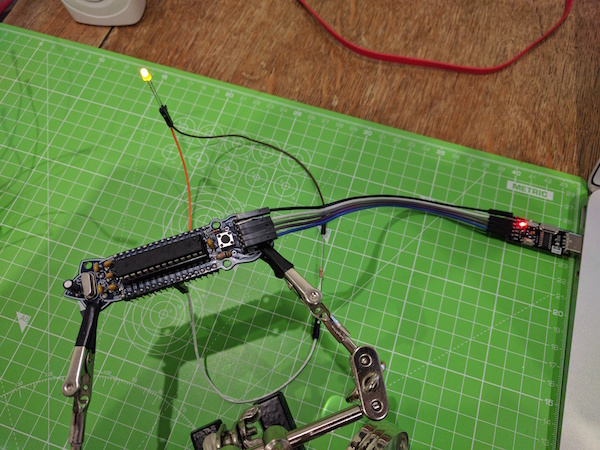
Now the LED should be flashing:
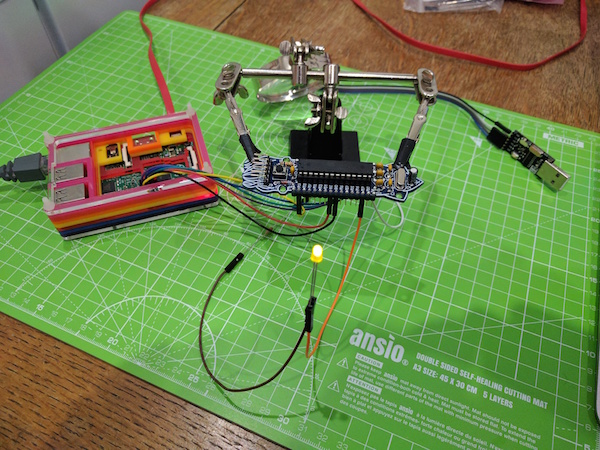
Except mine was flashing much slower than the 1 second interval specified by the code.
Setting the fuses
I eventually figured out that the cause of the slowness was an incorrect clock speed. Stock ATmega328 chips are configured to use an 8Mhz internal oscillator clock and have a “clock divide” setting enabled which divides the speed by 8, so it was ignoring the 16Mhz external crystal clock on the Cuttle and running at 1Mhz instead.
These settings are stored in “fuses” on the chip. This article has a really good explanation of the various settings that you can change:
The current fuse settings are displayed by avrdude each time it connects
to the chip, so we can use the output from earlier when we confirmed it was
connected correctly. To find out what the fuses should be changed to I
looked in the boards.txt that comes inside the Arduino IDE and found the
configuration for an Arduino Uno:
uno.bootloader.tool=avrdude
uno.bootloader.low_fuses=0xFF
uno.bootloader.high_fuses=0xDE
uno.bootloader.extended_fuses=0xFD
uno.bootloader.unlock_bits=0x3F
uno.bootloader.lock_bits=0x0F
uno.bootloader.file=optiboot/optiboot_atmega328.hex
The lock and unlock bits can be ignored. You should only change them if you know what you’re doing. We can compare the difference in settings by using an online calculator:
The summary of the differences is:
- disable clock divide
- use a 16mhz external crystal clock
- use a bootloader with the sizes relevant for Optiboot
- enable brown-out detection at 2.7v
You can write these changes with:
avrdude -p m328 -c linuxgpio -U lfuse:w:0xFF:m -U hfuse:w:0xDE:m -U efuse:w:0xFD:m
Depending on what version of avrdude you’re using this might fail with the
following error:
avrdude: verifying ...
avrdude: verification error, first mismatch at byte 0x0000
         0x05 != 0xfd
avrdude: verification error; content mismatch

avrdude: safemode: efuse changed! Was fd, and is now 5
Would you like this fuse to be changed back? [y/n]
Answering y is pointless because it will just hang. Don’t panic though. It
has written correctly, but there’s a bug in how the value is read
back. Only the last three bits are used for the extended fuse so the two
values are functionally equivalent:
0xFD: 1111 1101
0x05: 0000 0101
            ^^^
            |||
            ||+-> BODLEVEL0
            |+--> BODLEVEL1
            +---> BODLEVEL2
Now your LED should be flashing at the right speed and you can can use the standard serial headers to connect the board to the Arduino IDE and upload new sketches: