Replacing a Heating Controller
Our hot water system stopped hot watering on Christmas Eve. What follows is how I fixed it. For context this is a central heating system in a UK house with a conventional (not combi) boiler and unvented hot water tank.
The usual warnings apply. Electricity is dangerous - make sure you’ve isolated the supply and that the contacts are really dead. Gas is even more dangerous - do not open your boiler.
Symptoms
The controller was power cycling whenever it was calling for heat which was also causing the boiler cycle. This seems to be a common fault with this model of Honeywell ST9100C controller.
Some people have reported that disabling the backlight on the controller has worked as a temporary fix but it made no difference for me. Looking inside the controller revealed heat damage from the capacitors, which matched the symptoms and diagnosis of this ST9400C from Big Clive.
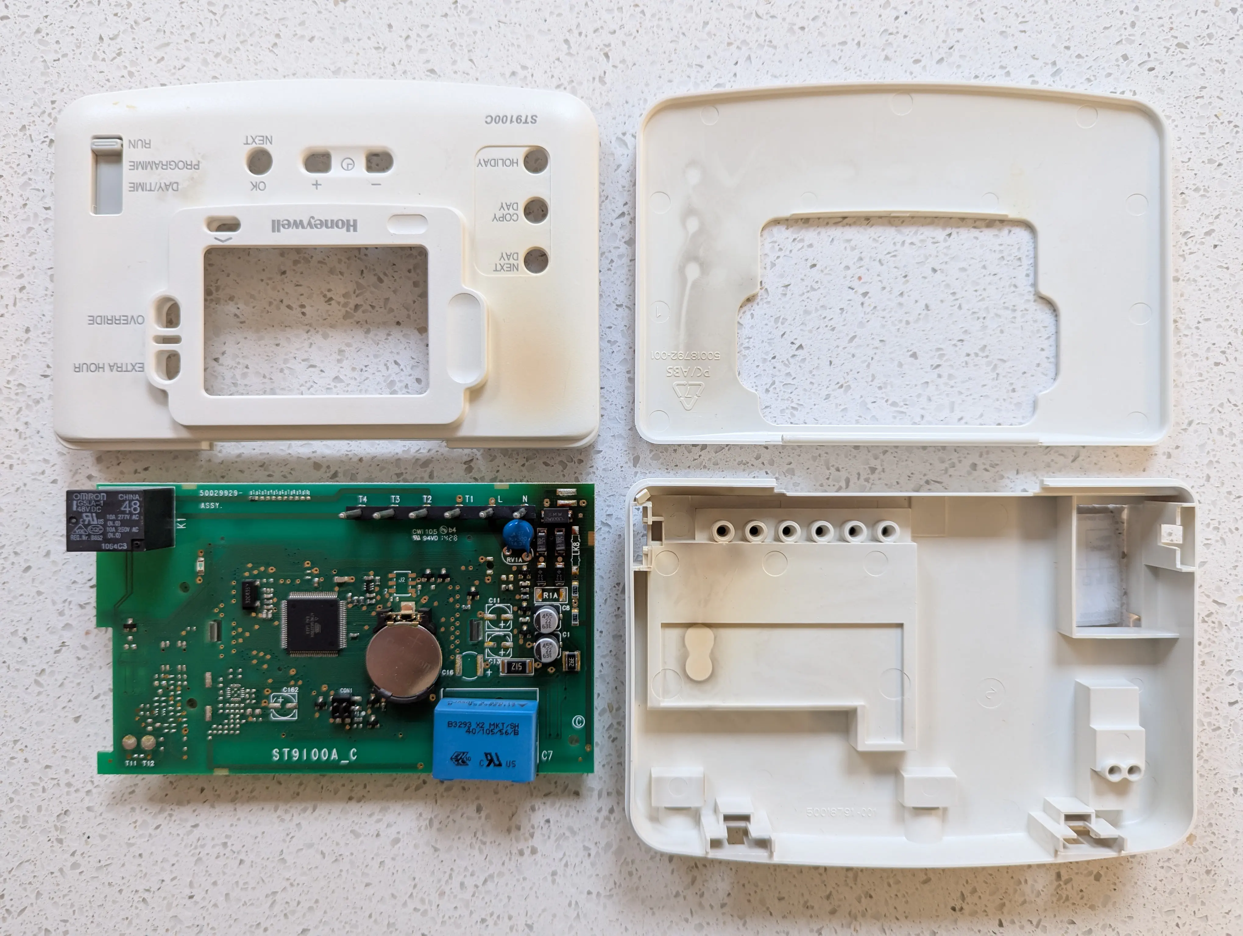
I wouldn’t be able to get any replacement components over Christmas (RIP Maplins). So my goal was to understand enough about my heating system to limp through Christmas and replace the broken controller as soon as possible.
Schematics
The first step was to make sense of the spaghetti junction that connects all of the heating components together. Whilst trying not to be too distracted by the badly terminated wires, which I’ll tidy up in the process.
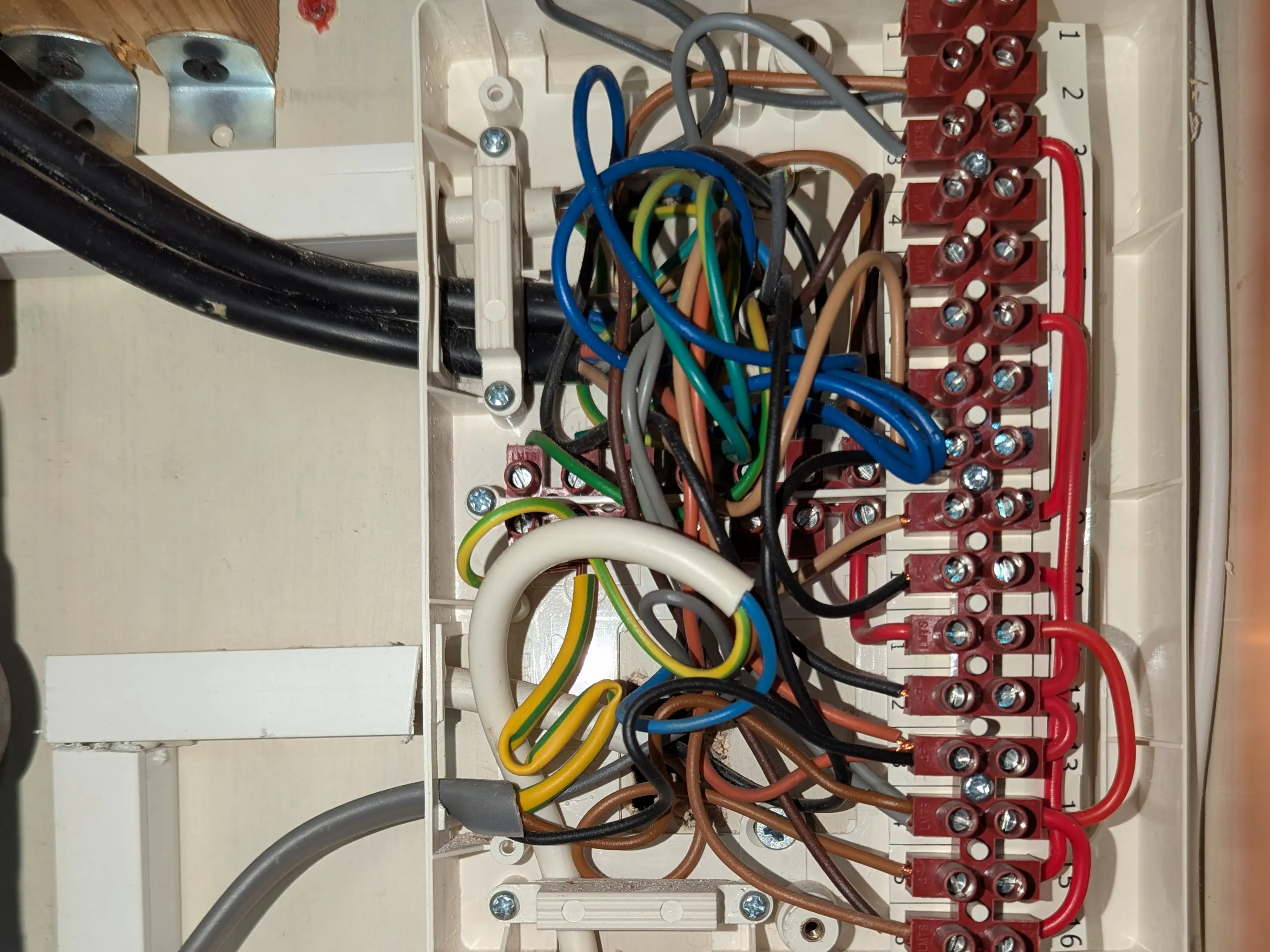
I started drawing it by hand. Not all the component terminals were easily accessible (e.g. the boiler requires removing the casing) so I just noted the colours of the wires coming from them and worked backwards from there.
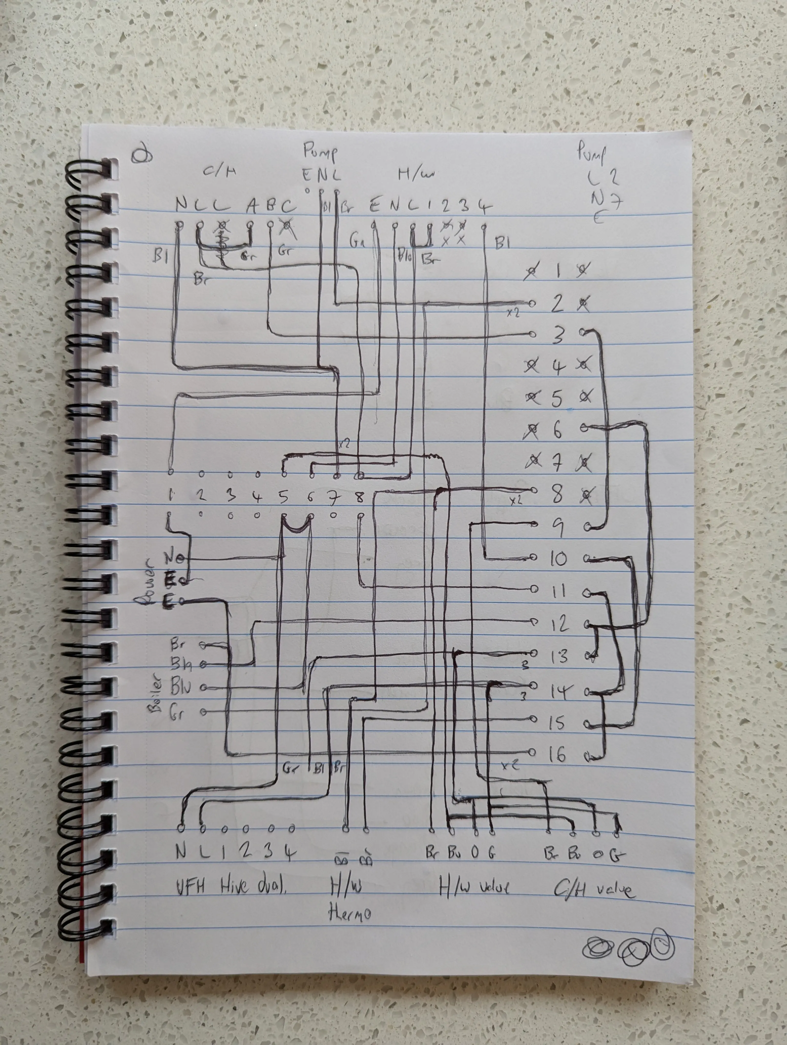
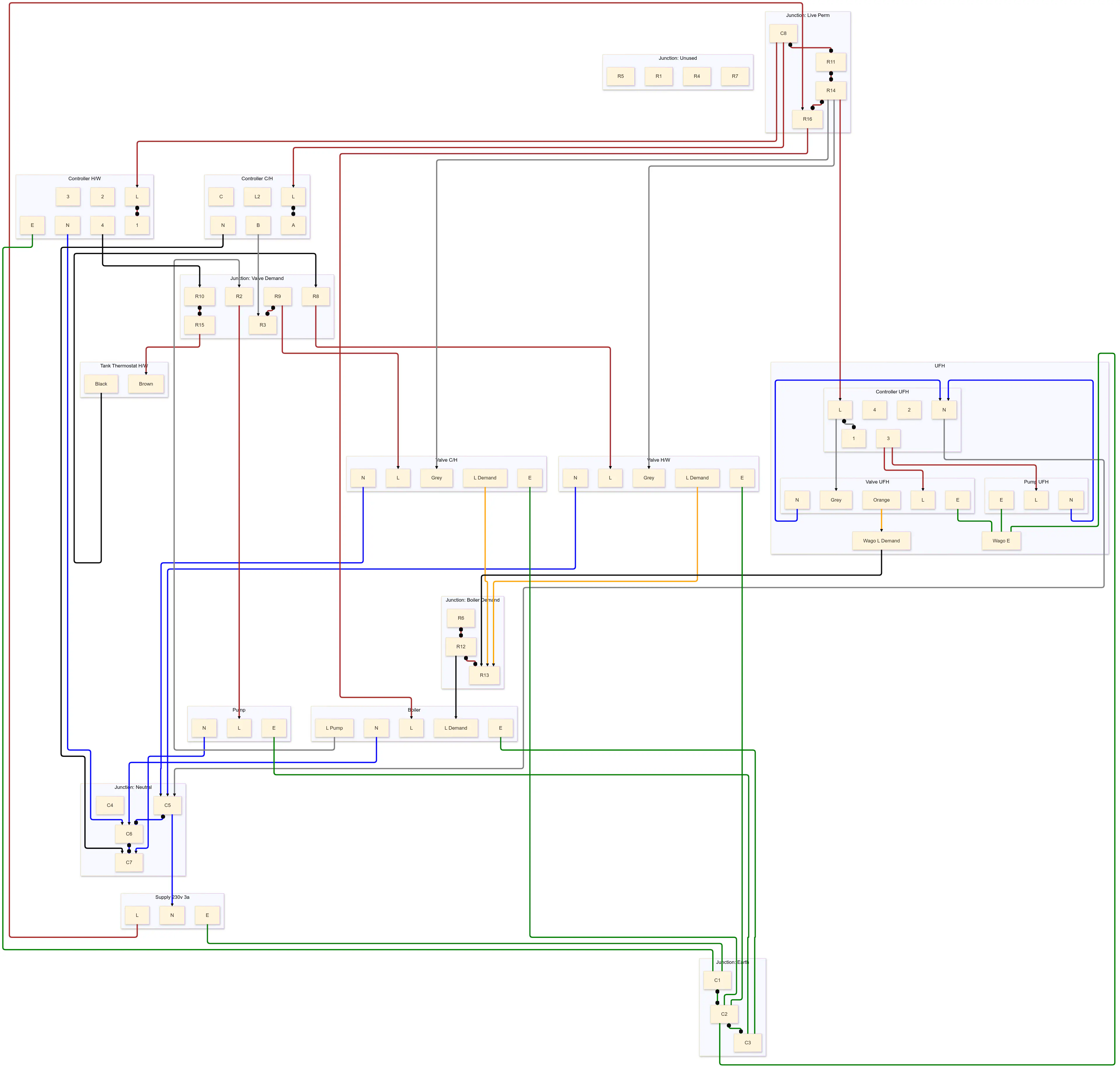
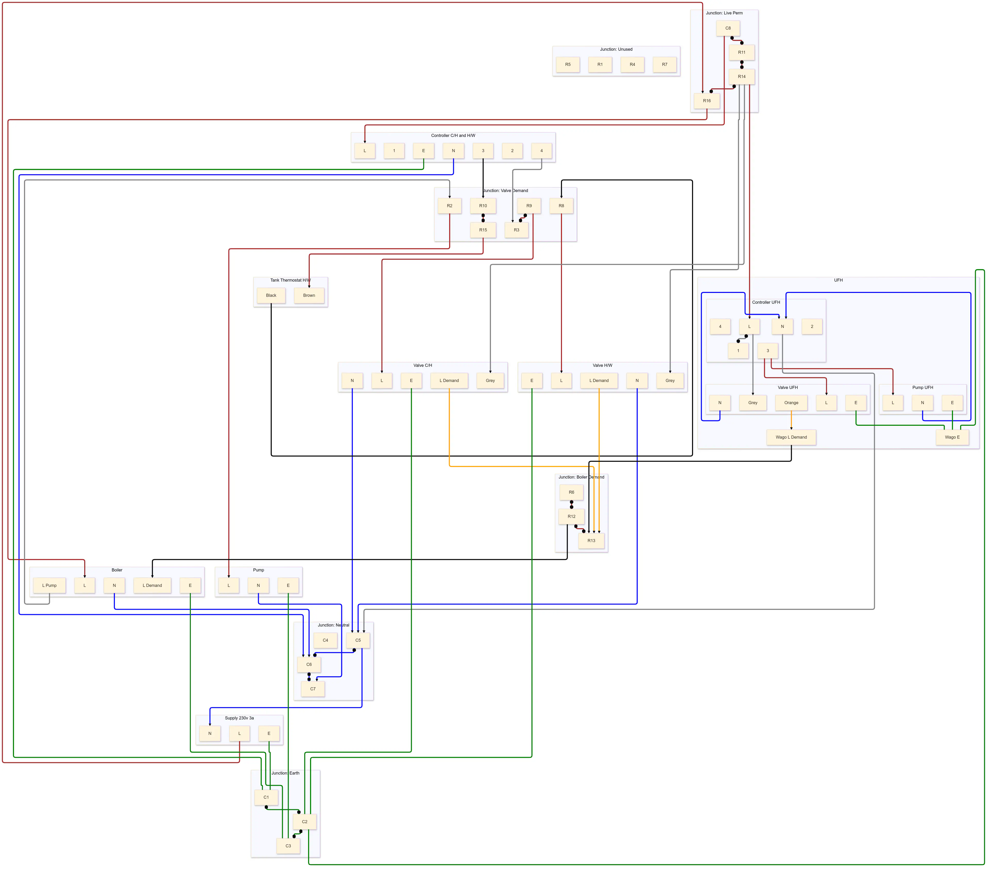
This gave me a solid point of reference but it was very hard to follow at a glance so I converted it into a Mermaid diagram with the appropriate colours for the wires. It’s hard to tell from the static render of the diagram but this made it possible to group the junction connections and provided some automatic hierarchy.
Key learnings
Based on this, I was able to figure out a simplified flow.
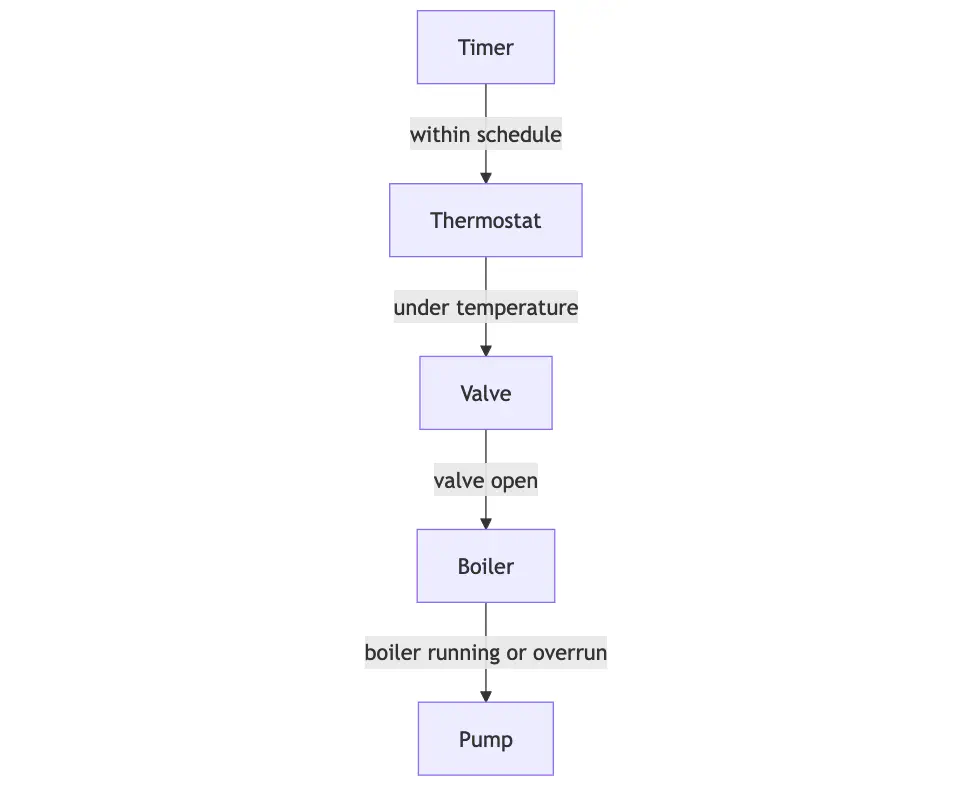
The timer and thermostat for the heating are part of the same controller, albeit with a wireless sender and receiver acting as a relay. The thermostat for the hot water is a separate unit that’s mounted on the tank and just acts as a switch.
Most of the components take and pass a switched live signal to indicate the demand for heat. My boiler and the rest of the system uses 240v for switched lives and unfortunately doesn’t support OpenTherm, but some newer boilers use lower voltages like 24v.
The boiler is responsible for telling the pump when to run. This happens both whilst the boiler is on and for a short period after the boiler has stopped, known as “pump overrun” to dissipate the build up of heat.
The valves are responsible for telling the boiler to start once the valve is open. This prevents the boiler from staying on if a valve gets stuck closed, which is a common failure point.
Our system has an additional zone added for underfloor heating in an extension to the house. This uses a Zonal Regulation Unit which works slightly differently in that it has its own pump but it only operates when the valve is open and a thermostat has detected the right temperature of water from the flow. It mixes the flow with existing water in the UFH system to achieve a temperature suitable for the flooring.
Workaround
The valves have a manual locking switch on them which opens the valve when there is no demand to the motor. It’s common for this to not engage the switched live to the boiler.
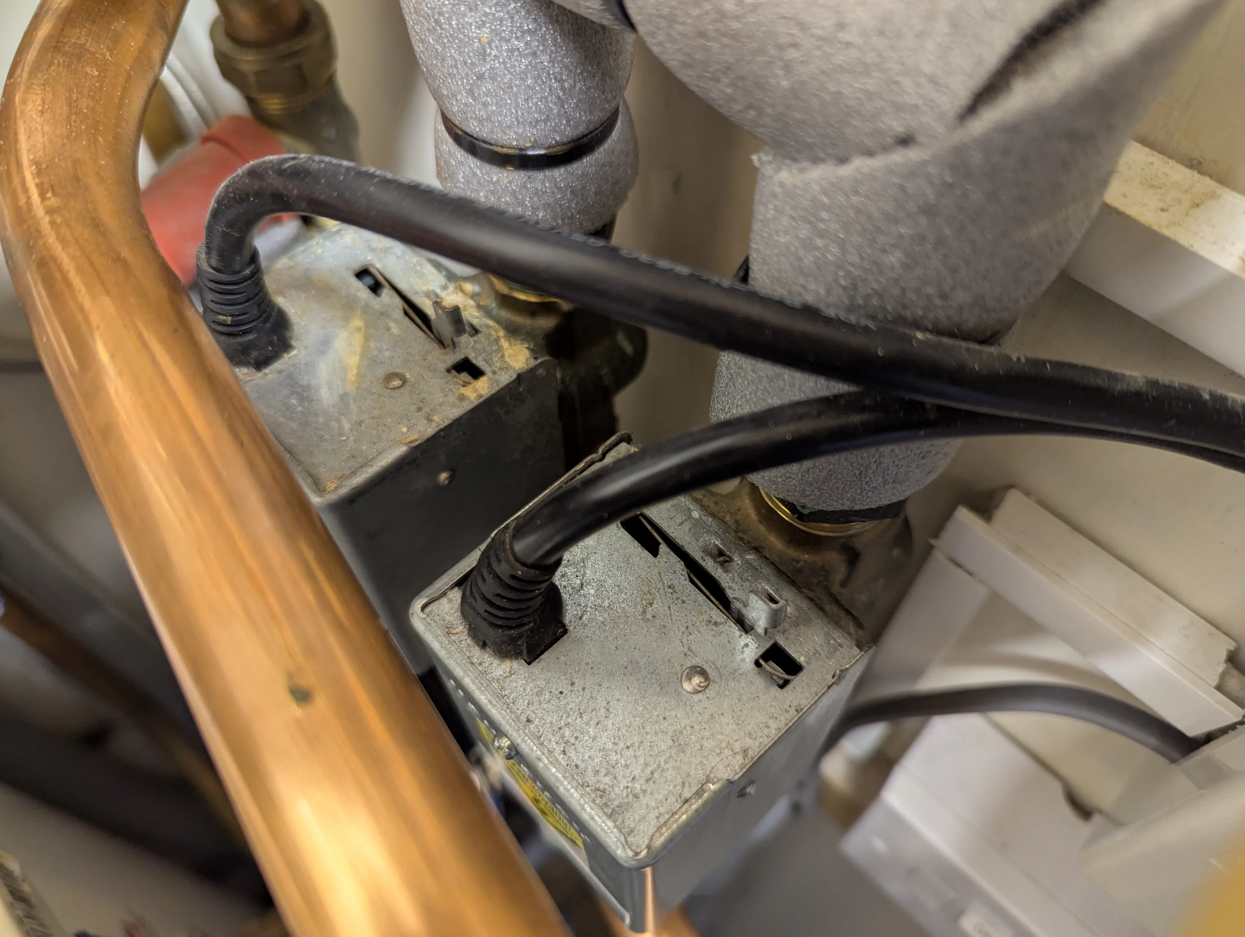
I could workaround our broken hot water controller by manually overriding the valve whilst another zone was calling for heat. It wouldn’t be regulated by the thermostat so I had to be careful not to run it for too long and overheat the tank. This gave me a couple of days reprise while the shops were shut.
Replacement
We already had a Hive controller on the UFH zone, which has proved useful for remote control and tracking efficiency. So I planned to replace the broken hot water controller and existing heating controller with another Hive controller.
For some reason the contractor that built the extension bought a dual channel receiver (heating and hot water) for the UFH zone when it only needed a single channel (heating only). So I could move the dual channel receiver to replace the existing heating and broken hot water controllers, and buy a new single channel receiver for the UFH.
Not that there is any price difference between Hive’s single and dual channel receivers. I already had a Hive Hub, so that brought down the cost a bit. Hive also make a “mini” product which is cheaper and has a slightly simplified thermostat, but provides the same receivers and same functionality through the app.
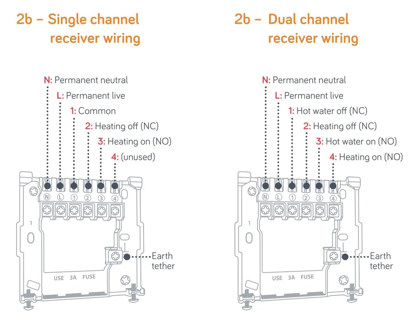
Hive receivers are wired as follows.
The old hot water controller used the same common backplate design that the receiver slots onto. However, it was wider than necessary for the Hive receiver, so it made sense to replace it at the same time. Thankfully there was already a 5 core cable in place with enough slack to reinstate the unused core because I could only buy new cable in 10m coils at short notice.
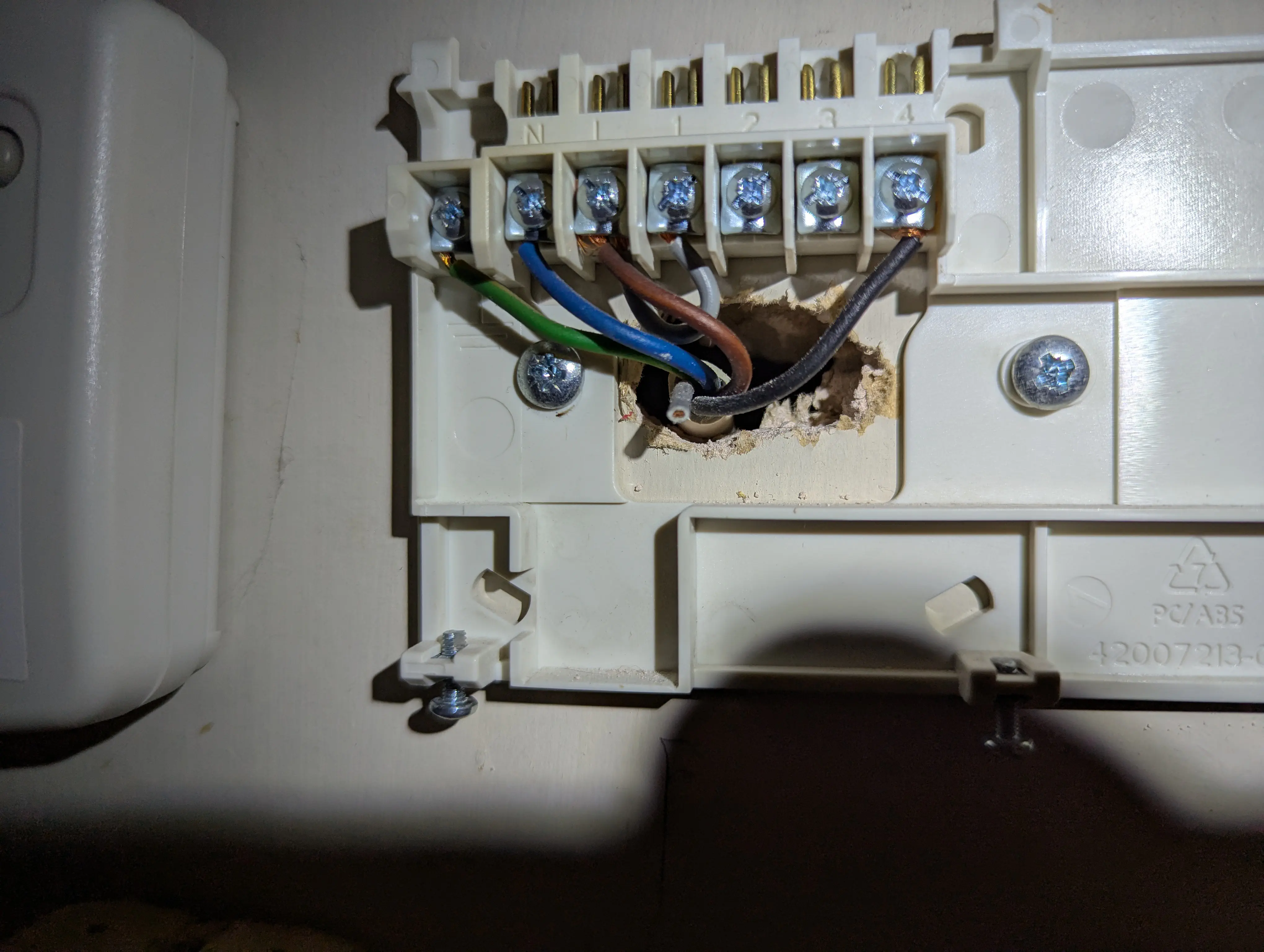
For the dual channel receiver I needed to swap the cores over from the old hot water controller, connect the additional core to where the old heating controller demand was, and remove the old heating controller.
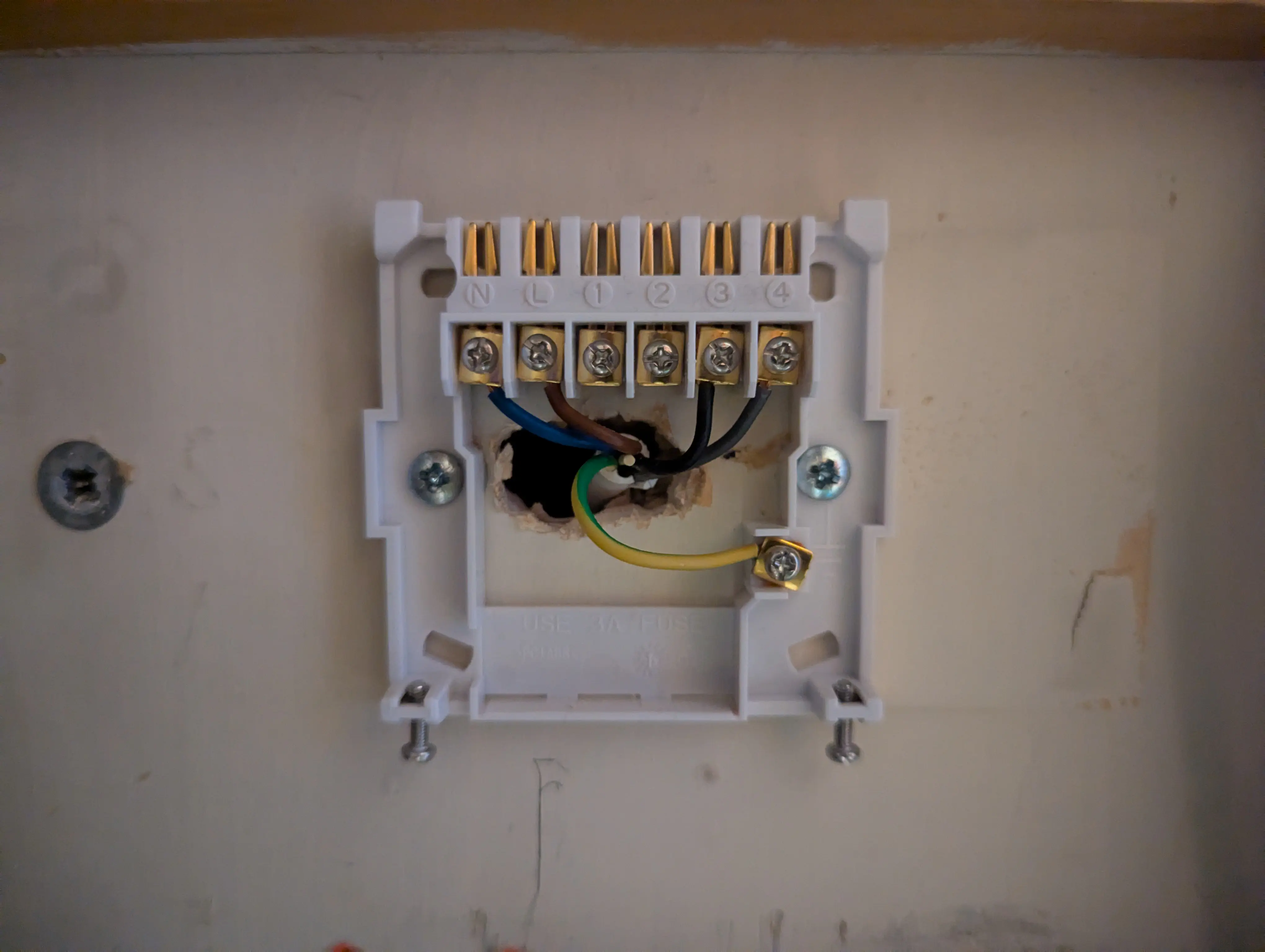
For the single channel receiver the heating demand moved over one contact to “heating normally open”. It also needed a link between live and common because unlike the dual channel receiver, which only switches at 240v and has a hardwired common internally, the single channel receiver allows you to choose the voltage from the common terminal.
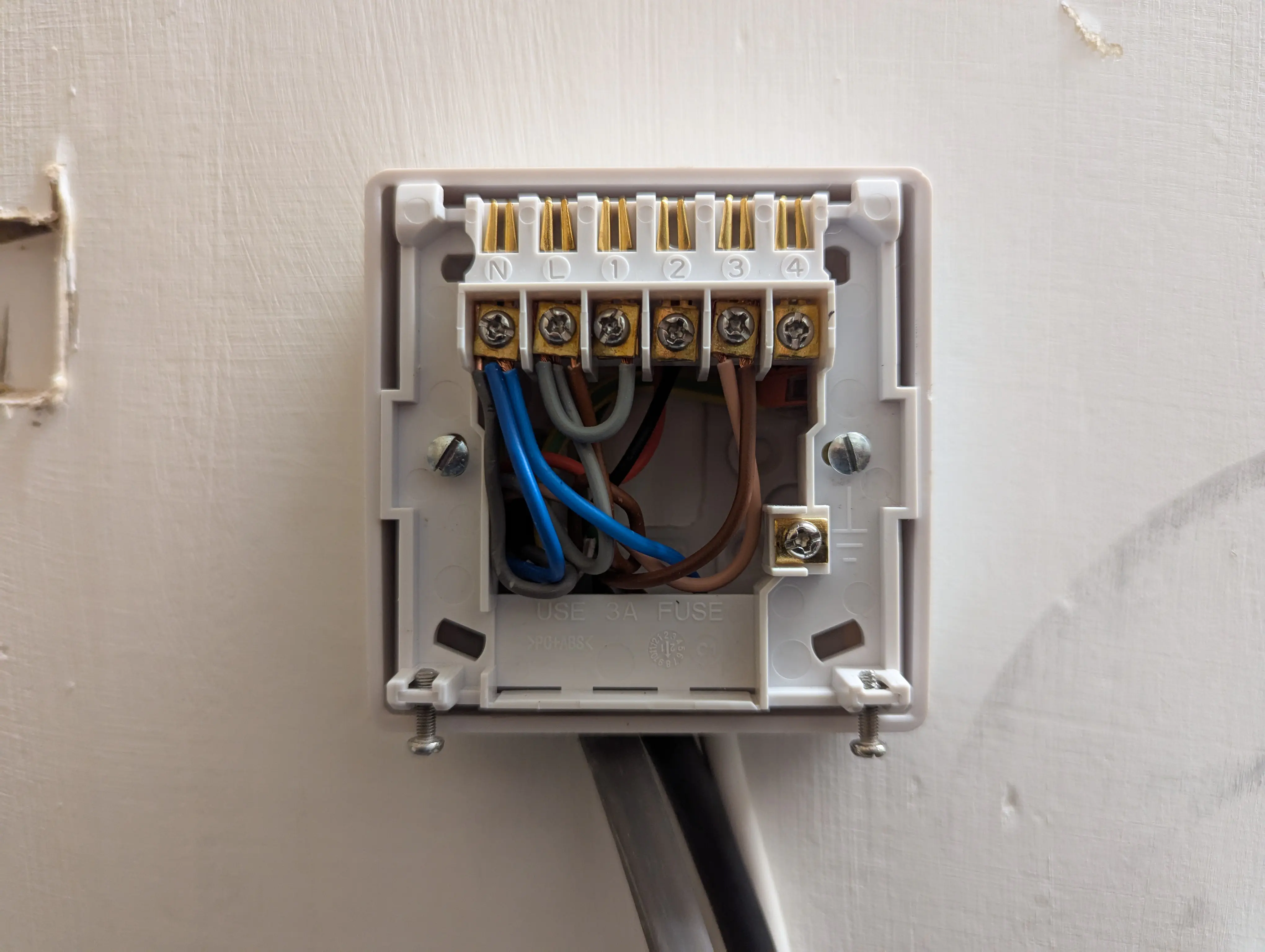
Conclusion
The final diagram looks a little bit simpler now that there’s one less controller.
I put the old but still functional Honeywell heating thermostat and receiver on eBay where it sold for more than I had purchased the new Hive for. I can only guess this is because people want to replace like-for-like when they break instead of drawing diagrams.
So the project came in at £6 profit and I understand it better for next time.